Solar shield

TI Launchpad
A few months ago I started using the TI Launchpad, which is a great piece of hardware for rapid prototyping. Nevertheless I found difficult to set it free, to let it fly solo, as there are few off-the-shelf options in order to provide the required voltage to this little board, so I decided to built my own one and this way learn a little about PCB design.
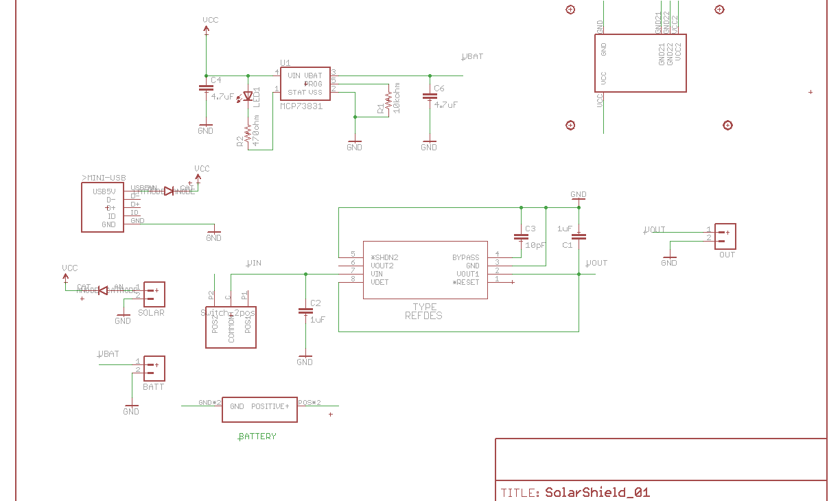
The board relays on a AA size lithium battery for power supply. The power is then converted to 3.3V via a LDO regulator, why did I choose this output voltage? Although the launchpad board provides 3.6 V I decided to switch to 3.3V for a couple of reasons:
- The msp430g2xxx chips (I don’t know it this applies to the rest of msp430 chips) work also with 3.3V, up to the maximum frequency of 16Mhz, so there should be not problem of performance lost using this voltage.
- There are lots of sensor in the markets using 3.3V.
- Using a LDO requires that the power supply (In this case the lithium battery ) voltage is over the desired output voltage (3.3V) , with some margin wich depends on the specific LDO (in this case around 0.15 V). As the battery normal voltage is around 3.7V is unfeasible to provide 3.6 with the current LDO, therefore 3.3V is a more convenient output voltage.
Nevertheless, using a LDO with a lithium battery to provide 3.3V has the drawback that the battery voltage should be over 3.45 V. As the battery discharges it decreases it voltage, but this voltage is at the very end of the battery life so little juice is lost.
This board is intended to be used with a 14500 lithium battery, this batteries have a capacity around 900mAh and can be buy at relatively cheap prices. Furthermore, models with integrated protection circuit are also available.
The battery is charged via a mini-usb port but I added an input for a solar panel, isolated from the usb via diodes. Moreover, other power sources could be connected as long as their voltage is between 4.5 and 6V, this also applies to the solar panel. Right now the charging current is set to 200mA . The charging is controlled by a microchip MCP73831.
Finally I added a switch in order to shutdown the power supply whenever is desired.
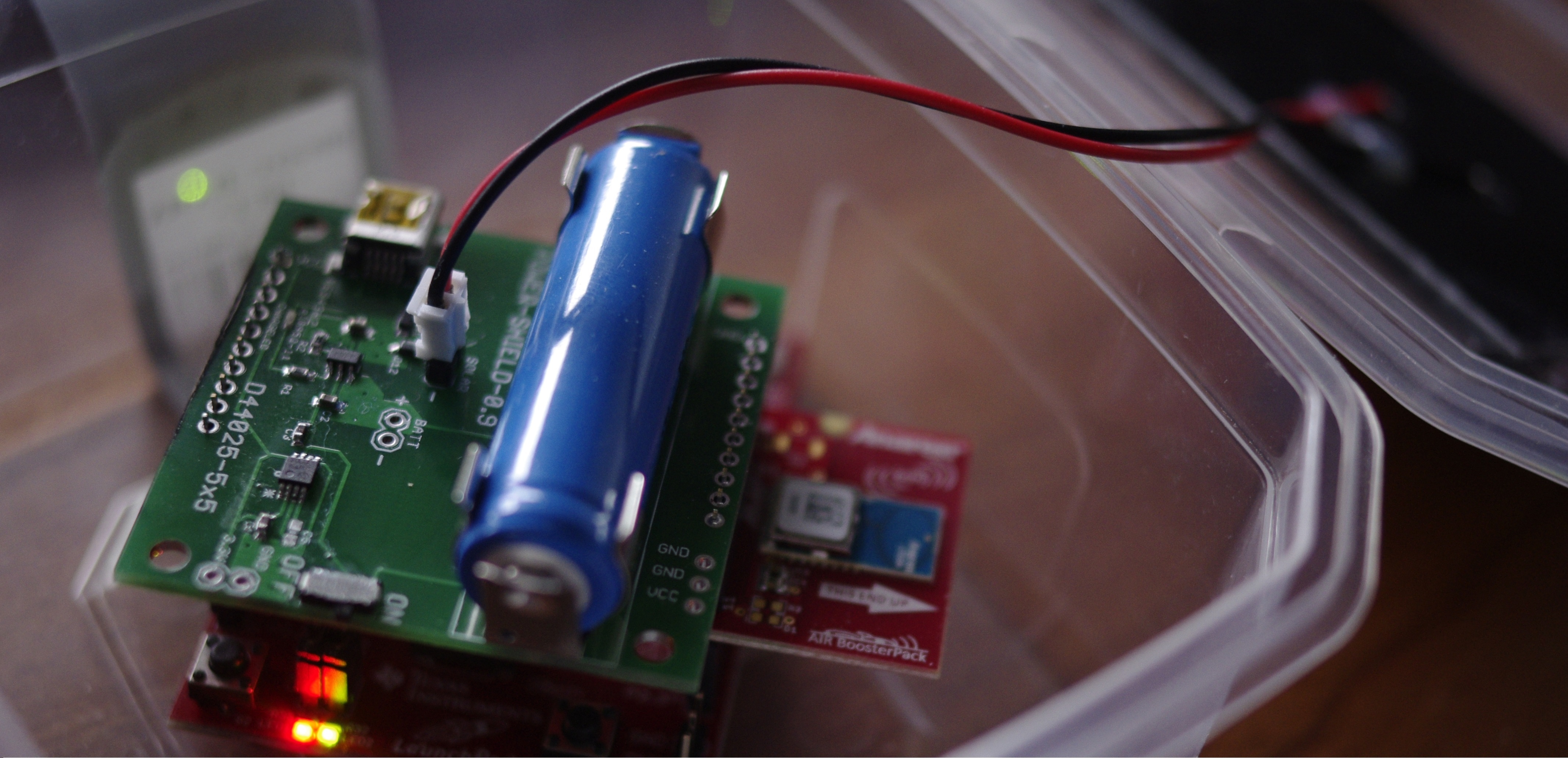
On the air
I went a little bit further, so I mounted an air booster pack, plug in a solar panel to the board and packed everything in a plastic box so I can lay it outside, waterproof!! :) . With this configuration I was able to read external temperature from my computer and switch on the green led you see in the photo above. Nevertheless, the possibilities go beyond this simple example but I still have to learn how to use other features of the air booster pack and do some real programing. Unfortunately, at a first look documentation doesn’t look very friendly :s.
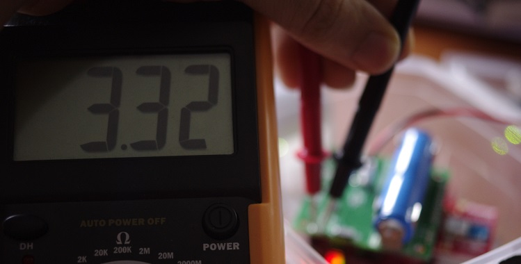
I took several reading of the output voltage, obtaining stable measurements of 3.32V I do not know if this offset is due to the LDO tolerance or the cheapo multimeter. Right now it seems to work properly and the charging led was on when I placed the box outside. The LDO is able to supply up to 300mA which it is more than enough for this kind of application. If more juice is needed the battery can be connected directly, for example to an H-bridge, while maintaining the 3.3V supply to the mcu.